CoF, K Factor and the Trouble With ISO 16047
by:
John Medcalf | Principal Engineer
Peak Innovations Engineering
9934 N. Alpine Rd., Suite 104
Machesney Park, IL 61115 USA
Experts in fastener engineering know bolted joints can be troublesome. But given the lack of attention they frequently receive both during design and assembly, it is surprising they are not more troublesome than they are. I would argue the reason is, historically, many bolted joints have been over designed. However, as industries push for efficiency and lighter weight assemblies, bolted joints are asked to do more with less. Improving fastening efficiency requires increased confidence in the clamp load achieved with a given tightening strategy. Torque control is still the most commonly used tightening strategy, and while advances continue to be made in the accuracy and reliability of tooling, it is still only as good as the consistency in the relationship between torque and tension.
It can easily be forgotten that screws are one of the six simple machines (along with pulleys, levers and the like). The screw can take a small applied rotational force (torque), and multiply it into a large linear force (clamp load). However, only about 10% of the applied torque actually goes into creating clamp load, while the rest is consumed by friction. The numbers will vary based on joint components, but approximately 50% to 55% of torque is consumed by friction between bearing surfaces and 35% to 40% is consumed by friction between thread surfaces (and while losing 90% of your torque to friction may seem undesirable, keep in mind this is also the reason a nut stays tight and does not spin off immediately after you stop applying torque)! It then follows that controlling friction is the key to consistent clamp force at assembly. Zinc-aluminum flake coatings now come with a variety of formulations, lubricants and top coats to dial in torque-tension relationships, and topcoats have even improved the consistency of zinc electroplating. More and more OEMs are releasing fastener coating specifications now requiring specific torque-tension performance.
And while several different versions of the formula exist, ISO 16047—Fasteners —Torque/clamp force testing, relates applied torque to clamp force using the equation:
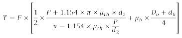
The variables of note here are:
• d2 – Basic pitch diameter of thread
• dh – Clearance hole diameter
• Do – Outer diameter of bearing surface
• F – Clamp force
• P – Pitch of the thread
• T – Tightening torque
• μb – Coefficient of friction between bearing surfaces
• μth – Coefficient of friction between threads
If the coefficients of friction are assumed to be equivalent, a coefficient of total friction can be calculated from the equation:
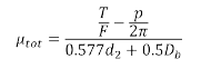
Where:
![]()
Because fastener geometry (size, thread pitch, bearing surface diameter, etc.) is accounted for in these equations, the calculations are intended to focus on the surface conditions—primarily influenced by fastener coatings. A coating applied to a hex cap screw should provide essentially the same coefficient of friction as if it were applied to a hex flange bolt. This is also the parameter coating applicators and chemical suppliers would control, as they do not have control over the end application or fastener geometry. So, if you want to know if your zinc-aluminum flake coating is formulated consistently, a coefficient of friction test would be beneficial. However, this is also the parameter most removed from how a part functions in an application, or how an engineer would correlate an assembly torque to a desired clamp load.
Fortunately, due to the direct relationship between torque and tension in the elastic tightening region (before a fastener begins to yield), the equation can be simplified all the way down to:
T=K×D×F
where D is the nominal diameter of the fastener. With T and F remaining the same, we now see “K” has replaced all of the terms relating to geometry and friction. K carries many names—the nut factor, K factor, torque coefficient, friction factor—but should not be confused with a coefficient of friction. This factor, while convenient to use, now incorporates all aspects of friction and geometry, and as such should be determined for each application based on testing. A K factor cannot be controlled by a coating applicator, and I have seen it inappropriately listed on fastener prints with no indication of the parts they should be tested with (which have a large influence on measured K factor). In order to test for K factor, all mating parts must be specified, and for the results to be meaningful, those mating parts should replicate the application as closely as possible. Now if an engineer has an accurate K factor for a given application, calculating the necessary tightening torque to achieve a desired preload is straightforward (see Figure 1).
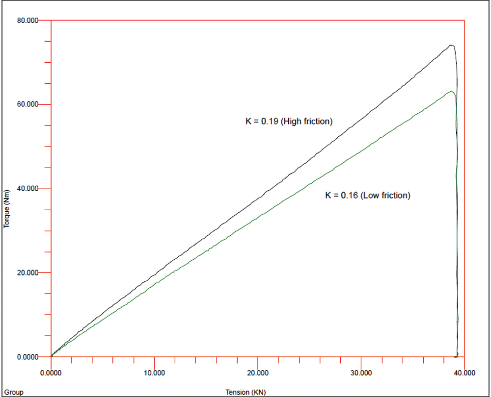
Fig. 1 Torque-tension plot of two fasteners.
Whether testing for coefficient of friction or K factor, torque-tension testing of fasteners is not overly complicated. The only required pieces of equipment are a device for measuring torque and a load cell or other device for measuring clamp force (see Figure 2). However, to get meaningful, repeatable results, a strong attention to detail is required. Torque and clamp force devices must be accurate within the desired measurement range. Whether the torque measuring device is a wrench or a transducer, proper usage is essential to ensure the reading accurately reflects the torque actually applied to the fastener (think axial alignment, interpretation of readings if using a wrench, etc.). Tightening at a constant speed is also desired. Clearance or rigidity of fixtures can impact results, and of course it was already discussed how much the mating fasteners (nut and washer for example) will influence coefficient of friction or K factor results. So, in an effort to provide guidance on these topics, ISO 16047 was created as an international standard for testing the torque-tension performance of threaded fasteners. It gives direction on accuracy of equipment required, default testing speeds, fixture design, test hardware and calculation methods for both coefficients of friction and K factors. It provides two paths: testing under standard conditions and testing under specific conditions. The set of instructions for testing under standard conditions is meant to evaluate the performance of a single component, i.e., what is the coefficient of friction of a lot of bolts. In this case, the standard gives some direction on standardized nuts and washers to be used so that, in theory, anyone testing those bolts should get the same results. Testing under specific conditions refers to more application-specific testing—for example, how does a specific assembly of bolts, nuts and washers perform together? In this case, all of the hardware used and tightening speed need to be agreed upon between the contracting parties.
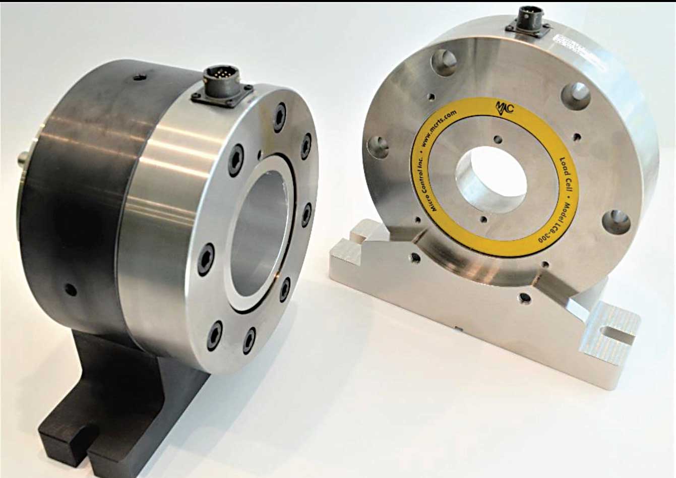
Fig. 2 — Load cells for torque-tension testing (Courtesy of Micro Control Inc.).
Just as more and more coating specifications are requiring specific torque tension performance, many of those specifications also refer to ISO 16047 as the test method to be used for evaluation. A number of these specifications require the coefficient of friction to be within a certain range, and since it should be independent of geometry, they use surrogate hardware to further standardize testing. The surrogate parts either get coated along with the parts of interest or get coated through a specific process. Testing of the surrogate parts then is used to qualify the production parts or the coating process itself.
While this all sounds like a logical exercise, the challenge is that ISO 16047 actually leaves a lot of room for options, and very few specifications that refer to it provide sufficient direction to remove those options. For example, when testing bolts, ISO 10647 gives direction on the mating nuts and washers to be used. However, it gives the option of two different washer hardness values, which the party performing the test may choose between “according to experience.” Also, the finish of the nuts and washers may either be plain or zinc electroplated, with no direction on which is more suitable, or the effect the two different coatings may have. While mating parts must be degreased, the degreasing procedure is also unspecified, only requiring that it is done by ultrasonic means. Tightening speed is controlled, but for sizes of M3 to M16, a range of 10 RPM to 40 RPM is allowed. While each of these variables may seem inconsequential on their own, do we expect that an M10 bolt tested with a zinc electroplated nut and high hardness washer, degreased with acetone for one minute, tightened at 10 RPM would give the same results as if it were tested with a plain nut and lower hardness washer, degreased with isopropanol for 10 minutes, tightened at 40 RPM? Peak Innovations Engineering recently did a study for the ISO fastener committee responsible for the 16047 standard, and showed that even just varying the washer hardness, with all other parameters held constant, changed the measured total coefficient of friction from 0.162 to 0.176 for one set of hardware—an almost 9% difference.
Now that the challenges with ISO 16047 are known, two ways its use can be improved are provided. First, the ISO fastener committee responsible for the document (TC 2 / SC 11), is aware of these challenges, and a project has been initiated to improve the standard. The intent is to remove as many of the options and variables as possible, so less experience or interpretation is required, and repeatability and reproducibility of results can be improved. Currently, Peak Innovations Engineering is participating in a study to determine if more tightly controlling the test washers and test nuts may reduce variability in results. However, the revision of ISO 16047 will be a multiple year process, with collaboration from industry experts from multiple countries. In the meantime, it is up to users of the standard to understand the limitations, further specify those requirements that the standard leaves open and use reputable sources for obtaining results.
Finally, it cannot be overstated how the ISO 16047 test results must be taken for what they are—a simplified version of an actual joint at best. Even if bearing surfaces and nut-member threads are accurately represented with test coupons, an ISO 16047 test will not replicate joint stiffness, which prevents the determination of true yield points, torque-angle tightening strategies, or potential joint relaxation. Examination of these parameters are all better served through in-joint testing with technologies such as ultrasonics (see Figure 3).
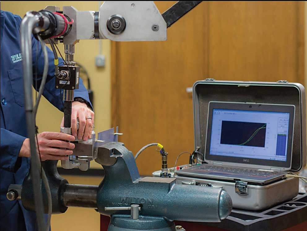
Fig. 3 — In-joint ultrasonic torque-tension test.
In summary, the combination of advances in fastener assembly equipment and coatings can allow for increased confidence in clamp load achieved at assembly. This enables designs to use less or smaller fasteners by better utilizing their strength capacity. Benefits are reduced weight, improved assembly efficiency, and overall reduced costs. For all of this to be true, though, a sound understanding and control of fastener torque-tension performance, whether through coefficients of friction, K factors, or in-joint performance tests is required. While ISO 16047 serves as a guide for how to test for some of these parameters, it cannot stand alone without knowledge of its limitations and loopholes. Peak Innovations Engineering understands these limitations and can help assess what testing is best suited to improve your fastening performance.
Company Profile:
Peak Innovations Engineering has a highly technical team to design, test, validate, and enhance the bolted joints within your product application. Joint development and testing are all we do, so we do it better than other available options, both internal and external. Why consume your resources engineering and problem-solving areas that are secondary to your core responsibilities when we can take care of them quickly, definitively, and cost-effectively? www.pieng.com