Part 1: The Three Least Understood Truths in Bolted Joint Design
Peak Innovations Engineering
9934 N. Alpine Rd., Suite 104
Machesney Park, IL 61115 USA
In fastening, as in most endeavors, the most common misconceptions related to the most fundamental principles. These errors are commonly made simply because their universal nature provides the greatest opportunity for making them. For example, the reason that most auto accidents occur within a small radius of the driver’s home is not that those streets are the most dangerous, but because they are the ones the driver travels on most often. Similarly, one of the main reasons these fastening misconceptions exist so widely is because they are so basic to the use of threaded fasteners. Therefore, those with less experience assume it is common knowledge. What follows is hopefully some of what you always wanted to know about bolted joints but were afraid to ask.
1. Tension, rather than torque, is the quantity that should determine how “tight” a structural joint should be.
The tensile capacity, and generally the longevity of bolted joints in structural applications, are determined by the force with which the bolt “squeezes” the components being secured, referred to as the clamp load. The pressure exerted by the joint on the bolt, an equal and opposite reaction to the clamp load, is the bolt tension. Tension is generated in the bolt when one set of threads is turned relative to another set. This movement wants to shorten the distance between the bearing surfaces of the two parts (usually the face under the nut and bolt head), but the stack of components between those faces provides a great deal of resistance to allowing the bearing faces to move closer to one another. So the faces stay in about the same relative position, and the length of fastener that lies between them stretches instead – generating both tension in the bolt and the mating clamp load on the joint. How does this tension relate to the torque needed to rotate the fastener? Actually, it is a direct relationship most commonly expressed as T = KDF, where T, K, D, and F are the torque, nut factor, nominal bolt diameter, and the force (or tension) respectively. So for a given bolt, torque is directly proportional to tension, with a factor K (often referred to as the nut factor or K factor)- the only variable that must be known to be able to calculate torque from tension, or visa-versa. Unfortunately, this K factor is a compilation of several friction components that vary with materials, finishes, pressure, geometry, and the speed of relative motion. It is therefore quite difficult to predict (even varying during the tightening), so assigning a value for a given joint can not be done accurately without experimentation.
So why not measure tension directly during assembly as a way to determine how tight is right? This is in fact a possibility and is done in limited cases. More often, the torque vs. tension relationship is established in the lab with the results used to establish target torque. However, bolt tension is more difficult and expensive to measure than the torque applied to generate that tension. So the most common method of testing involves tightening the bolt just beyond its yield point in the joint. At yield, bolt tension can be estimated based on the fastener’s proof load (similar to yield strength). This provides a method of estimating the relationship between torque and tension without directly measuring tension.
The take-away from this discussion is while tension is the quantity of interest, torque is easier to measure alternative, directly related to tension through a difficult to measure “K” factor. Therefore, the accuracy with which one can estimate tension from tightening torque can vary widely, with errors often ranging from 10% to 50% or more. It is important to note that this error has nothing to do with the accuracy of the torque wrench itself. The tool error is simply the uncertainty of how close the wrench’s torque reading is to the actual torque. The K factor uncertainty represents how well the input torque can determine the bolt tension. This error is in addition to the tool error and is generally much greater. For example, a torque wrench can have less than 1% error but not be able to tighten bolts within 50% of their target tension.
2. When an external tensile load is applied to a joint, the increased load is not directly added to bolt tension.
In simple terms, the bolt does not “feel” the entire external load. In fact, in most cases, the vast majority of this additional load is absorbed by the clamped joint members because the joint is usually much stiffer than the bolts. This is the reason bolts tensioned at or near yield can often resist significant external tensile loads, such as the head bolts in your car’s engine. At some point, however, the external load can be great enough that the clamp load on the joint is unloaded completely. Any additional load from this point will be entirely additive to the existing bolt tension. The balance between the forces acting on the bolt and the joint is generally displayed on a graph called a “joint diagram.” However, these diagrams are not clearly understood without some explanation and study, so we put together what we thought was a more easily understood illustration.
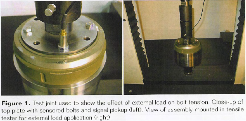 Using a component from an assembly on which we recently conducted some torque-tension testing, we performed a simple test showing the impact of external tensile loading on the bolt tension of a pre-loaded bolt. As shown in Figure 1, we modified the existing assembly by replacing the eight 5/16 – 18 socket head cap screws with four Grade 5 hex head cap screws. These fasteners were prepped with ultrasonic sensors to allow real-time measurement of blot tension in the joint. Adapters allow the test assembly to be mounted into a tensile tester.
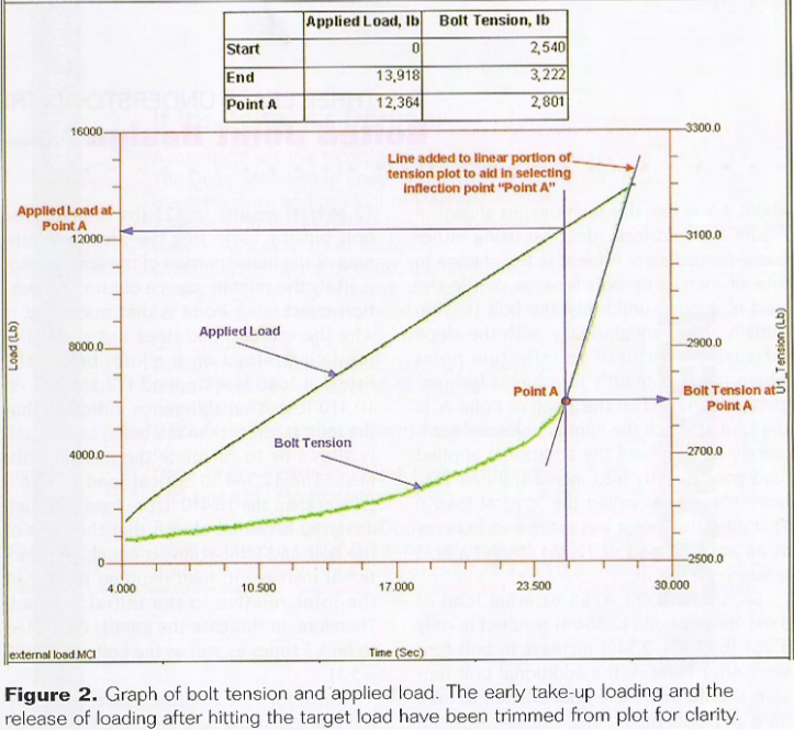 The bolts were tightened to a target preload of 2,500 lbs per bolt. The load was then applied to the joint via the tensile tester, while tension in one of the four bolts was monitored as shown in Figure 2.
Immediately evident is the change in the rate of increasing bolt tension. While the load is applied uniformly, the bolt tension initially rises very gradually, with the slope increasing a bit until an inflection point where it rises steadily in a linear fashion. That point, noted on the graph as Point A, is the load at which the joint is unloaded completely and 100% of the additional applied load goes directly into increasing bolt tension (sometimes called the “critical load”). That inflection point was estimated to occur at an applied load of 12,364 lb and a bolt tension of 2,801 lb.
So, up to Point A, an external load of 3,091 lbs per bolt (12,364/4) resulted in only a 261 lb (2,901-2,501) increase in bolt tension. After Point A, the additional bolt tension should equal the added external load on a per-bolt basis. The calculations are close to what was expected, as the additional 389 lb load per bolt {(13,918 – 12,364)/4} results in 421 lbs of increased bolt tension. Selecting the precise beginning of the linear portion of the tension plot is likely the primary source of error. A question concerning Point A that may arise is why the critical load does not equal the total clamp load that was initially applied (12,364 lbs vs. 10,410 lbs). That difference indicates that the joint is stiffer than the bolts and actually allows us to calculate the relative stiffness. The 12,364 lb critical load is 18.8% greater than the 10,410 lb pre-load. Through analysis, it can be shown that the ratio of the bolt and joint stiffness equals the fractional increase in load required to unload the joint relative to the initial preload. Therefore, in this case, the joint is estimated to be 5.3 times as stiff as the bolts (1/0.188=5.3).
Watch for Part 2 of this article, where we will discuss sizing fasteners and the impact of substitutions.
Did you know…?
- The one-piece carbon fiber fuselage of the Boeing 787 Dreamliner eliminates the need for 40,000 to 50,000 fasteners that would have been required with a typical aluminum design.
- Products regularly submitted for third-party testing and certification are subject to recall about one-third as often as those that are not.
- There are approximately 3,500 spot welds in the typical automotive sedan.
- An investigative panel determined the root cause of the fire that doomed the maiden flight of the Falcon I rocker was a fuel leak caused by a corroded aluminum nut. The Falcon I is a low-cost rocket system developed by SpaceX, a company privately funded by PayPal founder Elon Musk.
Company Profile:
Peak Innovations Engineering has a highly technical team to design, test, validate, and enhance the bolted joints within your product application. Joint development and testing are all we do, so we do it better than other available options, both internal and external. Why consume your resources engineering and problem-solving areas that are secondary to your core responsibilities when we can take care of them quickly, definitively, and cost-effectively? www.pieng.com