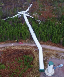
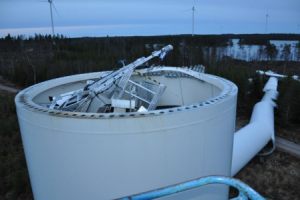
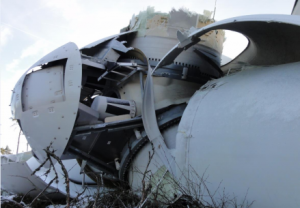
On Christmas Eve 2015 a 390 foot tall wind turbine located in the Lemnhult wind farm near Vetlanda Sweden collapsed when the bolts in the tower’s lowermost flange joint, containing one hundred M64 bolts, failed. The incident came into the news recently with the release of the Swedish Accident Investigation Authority’s final report.
Based on a short summary made available in English, the failure investigation yielded the following conclusions
-
 The bolts failed in fatigue, due primarily to wind forces. The root cause of the bolt fatigue was insufficient clamp load (bolt tension).
- There was no check the desired clamp load had been achieved.
- The torque tool was not adequately maintained
- The operator was inexperienced and not adequately trained
- Rain during installation altered the friction at the bolt’s mating surfaces, in turn decreasing the clamp load in the joint
- The municipality and the control manager limited inspections to the foundations
- The wind farm had previous problems with loose or broken bolts and were not reported to authorities
- The recommendations resulting from the investigation focused primarily on documentation, inspection and compliance with pertinent regulation.
 The bolts failed in fatigue, due primarily to wind forces. The root cause of the bolt fatigue was insufficient clamp load (bolt tension).
From the experience of conducting hundreds of tests on bolted joints over the last fifteen years, I recognized many important elements of this case are common to bolted joint problems across all industries.
From the experience of conducting hundreds of tests on bolted joints over the last fifteen years, I recognized many important elements of this case are common to bolted joint problems across all industries.
Fatigue fracture is the most common cause of sudden catastrophic failure of bolted joints. Fortunately, the appearance of the fracture surfaces is distinctive and metallurgical tests to confirm the visual diagnosis are widely available. But what initiated the cracks which ultimately led to failure? It is common to conclude the bolts were not to specification, which is rarely the case. Much more common, and as was determined in this case, is the force with which the joint is clamped together is not enough to handle the external loads acting on it. In this case, the primary external force is created by the wind causing the 400 ton wind turbine nearly 400 feet in the air to sway and put periodic bending loads on the bolts.
So if the bolts are as strong as expected, were the forces acting on the joint greater than projected? Manufacturers of highly engineered products carry high costs associated with failure or poor performance, like these turbines, generally do a good job of estimating these loads and apply a factor of safety to allow for uncertainty.
If the manufacturer does a good job estimating the external loads why would they design a joint not strong enough to handle them? Whenever we are speaking of a bolted joint, the answer is usually their calculations are based on a critical assumption difficult to confirm in practice. This assumption is how much force, or clamp load, did the bolts generate to hold the joint together. It is important to understand the difference between how strong the bolt is and how much clamp load it creates. Bolts have specified and easily verified requirements for strength; how much force it takes to pull it apart. However, by definition fatigue failure occurs by repetitively loading and unloading a component (the bolt) to failure at forces below the bolt’s ultimate strength. Think of bending a paper clip back and forth until it breaks. You are not nearly strong enough to pull it apart, yet you were easily able to break it. This wind turbine collapsed because the tower bolts failed like the paper clip did – just with much less bending over a much greater number of cycles.
 What does clamp load have to do with the paper clip example, and what exactly is clamp load?
Clamp load is created when a bolt is stretched. You can rotate a bolt into a nut or tapped hole by hand until the plate between the head and threads stop it. Then, with the assistance of a wrench you can continue to rotate the bolt. Because the threaded end advances into the mating threads, as long as the plates in between are not being crushed at the same rate the end of the bolt is advancing, then the bolt has to be stretched. Like a rubber band restricts a deck of cards from sliding back and forth, the tension in the stretched bolt creates a clamp load in the plates between the bolt head and the threads. A sufficient level of clamp load prevents fatigue failure by preventing two related events. First, clamp load prevents the clamped components from sliding relative to one another. Relative movement of structural joint components will eventually lead to failure in the vast majority of cases. Most of us have seen, and an unfortunate few have experienced, the results of insufficient clamp load applied to wheels on a car, truck or trailer. If the wheel is not clamped securely to the hub, the resulting movement causes the studs to bend back and forth by a small amount as the wheel rotates, eventually fracturing them and allowing the wheel to separate from the vehicle. In many cases of wheel separation some studs are still intact. Relative movement not only causes failure of the studs but also loosening of the lug nuts. The nuts often back off completely, so in some cases before all the studs fracture the wheel slips over the end of the remaining studs.
The second and more difficult to imagine risk of low clamp load that the increase in stress acting on the bolts from external loads is dependent on the clamp load in the joint. For example, if instead of wind loads acting parallel to the ground, imagine King Kong grabbing the turbine and pulling straight up on it again and again in an attempt to pull it out of the ground. With each pull a portion of force is transmitted to the bolts. In what is a counter-intuitive phenomena, the more the bolt is stretched at assembly (producing more clamp load) the smaller the portion of external pulling load is transmitted to the bolt. Reducing the min-max range of loads acting on components is key in reducing the likelihood of fatigue fracture.
So why is estimating clamp load generated at assembly so difficult? In most cases it is simply equal to the tension created when the fastener is elongated during tightening. Therefore, it is a common misconception an accurate torque wrench will produce an accurate estimate of clamp load. This is far from a true statement because the torque applied to a bolt is actually just a measure of the resistance to turning it. If the torque went into tensioning the bolt the relationship between torque and the initial bolt tension could be fairly accurately calculated. However, all but about 10-15% of the input torque is used to overcome friction under the head or nut and in the mating threads. The tightening process is very inefficient. As friction is the source of this inefficiency, many assume an accurate measure of the coefficient of friction (COF) would solve the problem. Because one can readily find COF tables on-line this would seem a straightforward proposition. However, the various geometries, surface finishes, coatings and lubricants in bolted joints represent a far more complex system than the two flat surfaces of raw material sliding against one another upon which COF calculations are based. In fact the torque tables would pop up in a Google search of “how much torque do I need for a ¼-20 bolt” are based on modified friction factors rather than COF and are still inadequate for critical joints such as the one in question. Why? Because saying the torque for all zinc-plated bolts can be defined by using a friction factor K of 0.20 would be the equivalent of instructing a house painter to use the color blue. There are too many variables to make a decision without testing the specific application to determine the most successful result.
 Recent advances in ultrasonic test equipment has made the previously unattainable goal of accurately measuring bolt tension without changing the joint or fastener or adding other components a reality. The ultimate goal of tightening standard bolts directly to tension in a production environment is not yet a reality, however the relationship between torque, angle of rotation and bolt tension can be determined through testing unmodified production hardware. From this information various tightening strategies can be compared to achieve the one will provide the desired clamp load with minimal scatter. The technique is also capable of monitoring changes due to time and temperature. This is important because being able to accurately determine clamp load at assembly does not mean one is home free. The clamp load existed in the tower joint when it failed was not the same as when the bolts were originally tightened. All bolted joints relax due to local yielding and/or material creep.
While certainly easier to list than to implement, it is always worth reviewing the three fundamental requirements of assembling structural bolted joints.
-
- How much clamp load is needed?
- What process of bolt tensioning (tightening) will consistently achieve it?
- How can we verify that we have achieved the desired clamp load, either by direct measurement or by process control?
If your answer to the first question is “I don’t have a number, but what we are doing now is working”, I suggest performing a test to measure what that number is and how much it varies. Then you will have a basis for comparison when what you are doing suddenly stops working.
You can not develop the most effective tightening process unless you are aware of what tools and techniques are available. There tends to be too much focus on the tool and not how it’s utilized and the tightening strategy applied. After some fairly rudimentary process development, a target clamp load can be much more accurately controlled with a $10 crescent wrench than a $20,000 programmable DC tool calibrated to ensure the stated 0.25% accuracy is applied to an installation torque that is taken from a reference table.
The method for verifying the clamp load is obviously very much dependent on the tool and tightening process used. However, one widely applicable observation is unless it is obviously damaged or malfunctioning, a tool is more likely to be a major contributor to not achieving desired clamp load as a result of it being setup or programmed incorrectly than it being out of calibration. For example, in our investigation of a wind turbine gear joint problem where bolts were occasionally being tensioned to failure at assembly, ultrasonic bolt tension measurement showed the presumed torque vs. bolt tension relationship needed adjustment. However, another major contributor to the bolts failing was the hydraulic torque wrench used for tightening had the wrong factor converting hydraulic pressure to the torque selected. The tool had previously been shipped back to the manufacturer who correctly found it to be in specification. This is not suggesting calibration is a waste of time but, as in this case, valuable time is often expended on an area is generally not a root case. This example also illustrates a strategy for improving the effectiveness of calibration. The more closely calibration can be performed in a condition reflecting actual use, the more accurate and valuable it will be. Calibrating the system rather than the sensor is usually more challenging but always beneficial.
In summary, a review of the Authority’s findings shows the first two bullet points encapsulate what happened and why. If the clamp load could have been reliably determined, the failure would not have occurred and the report would not have been requested. This direct relationship between cause and effect cannot be achieved by other corrective action, such as improved inspection, training and documentation.
By: David Archer
To view the accident report from the Swedish Accident Investigation Authority click here: http://www.havkom.se/en/investigations/vaegtrafik-oevrigt/olycka-med-vindkraftverk-i-lemnhult
*** Pictures are from the report